

2002 A8L W12 restoration
-
Fredde9912
- Posts: 24
- Joined: Tue Jul 21, 2026 5:30 pm
2002 A8L W12 restoration
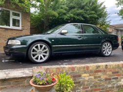
Finally found a long wheelbase W12. Decent options but has some issues among them the wheels, they just have to go asap. I will try to document some of the repairs here. If anyone has w12 experience please chime in. One of the big jobs I'm currently looking at is replacing the oil level sensor in the dry sump tank. Currently I can't find any instructions on this in ELSA. So if anyone has done this please comment
You do not have the required permissions to view the files attached to this post.
-
MikkiJayne
- Posts: 243
- Joined: Wed Sep 06, 2023 6:26 pm
Re: 2002 A8L W12 restoration
Ooh very nice, you don't see the crystal glasses very often! Those wheels though  What are you going to put on it? Gullideckels?
Is the oil level sensor not just bolted in to the bottom of the dry sump tank like it is in wet-sump engines?
What are you going to put on it? Gullideckels?Is the oil level sensor not just bolted in to the bottom of the dry sump tank like it is in wet-sump engines?
-
Fredde9912
- Posts: 24
- Joined: Tue Jul 21, 2026 5:30 pm
Re: 2002 A8L W12 restoration
Thank you. I have some S8 final Edition look alikes from a d3 I think they are pretty much the same but 0.5" wider and better ET just need to get some new 275/35/20. I quite like the look of the 18" on my other D2 but since the w12 used unique front brakes I will probably have to convert to something more avaliable. Looking at the Flying spur 405mm discs I think those would be bolt on with the Bentley calipers. That will require 19" but I don't think the D2 ever came on 19s so 20 will be nice. It's bolted to the side of the tank and from what the previous owner told me it's required bumper removal and complete removal of the tank to access it. Strange that there is no procedure in ELSA but I will probably just have to start taring it apart to fin out. Will try to make a post on the procedure since there seems to be no info online.
-
Fredde9912
- Posts: 24
- Joined: Tue Jul 21, 2026 5:30 pm
Re: 2002 A8L W12 restoration
Ow and btw are you still selling you brake blocks? I was very happy with the one on my V8 and this one will definitely need one aswell.MikkiJayne wrote: Wed Jul 22, 2026 7:37 pm Ooh very nice, you don't see the crystal glasses very often! Those wheels though
Is the oil level sensor not just bolted in to the bottom of the dry sump tank like it is in wet-sump engines?
-
MikkiJayne
- Posts: 243
- Joined: Wed Sep 06, 2023 6:26 pm
Re: 2002 A8L W12 restoration
I don't have any more brake blocks unfortunately. I could probably do another run of them if there was sufficient interest though.
Or, if you have a water-jetting company nearby I could share the CAD file so you can get it made yourself?
Or, if you have a water-jetting company nearby I could share the CAD file so you can get it made yourself?
-
Fredde9912
- Posts: 24
- Joined: Tue Jul 21, 2026 5:30 pm
Re: 2002 A8L W12 restoration
Ah too bad you don’t have any left but yes please send it I can probably find someone to make one. Maybe it could even be possible to 3d print one if the filament is strong enough.MikkiJayne wrote: Thu Jul 23, 2026 10:23 am I don't have any more brake blocks unfortunately. I could probably do another run of them if there was sufficient interest though.
Or, if you have a water-jetting company nearby I could share the CAD file so you can get it made yourself?
-
Fredde9912
- Posts: 24
- Joined: Tue Jul 21, 2026 5:30 pm
Re: 2002 A8L W12 restoration
Today I stared diagnosing the fridge. When testing it for the first time it would flicker on and off constantly but now it won't turn on at all.
I made a test harness to diagnose it away from the car with a spare battery. It showed no response. Checking with the multimeter I find that the on/off switch is doing its job and the circuit board is getting 12v power but the relay is not switching the fridge on. I checked the relay and believe it is defective.
I have ordered a new one and will see if replacing it fixes the issue. As a side note it's interesting to see the inside of the cool box. Strange to see the use of screw terminals and how the temp sensor is mounted. From what I have seen previously of the old school audi exclusive stuff this is probably from the factory.
The relay is a sun hold RAS-1215 if anyone knows how to properly test a relay like this feels free to comment.
I made a test harness to diagnose it away from the car with a spare battery. It showed no response. Checking with the multimeter I find that the on/off switch is doing its job and the circuit board is getting 12v power but the relay is not switching the fridge on. I checked the relay and believe it is defective.
I have ordered a new one and will see if replacing it fixes the issue. As a side note it's interesting to see the inside of the cool box. Strange to see the use of screw terminals and how the temp sensor is mounted. From what I have seen previously of the old school audi exclusive stuff this is probably from the factory.
The relay is a sun hold RAS-1215 if anyone knows how to properly test a relay like this feels free to comment.
You do not have the required permissions to view the files attached to this post.
Last edited by Fredde9912 on Fri Jul 24, 2026 10:32 pm, edited 4 times in total.
-
Fredde9912
- Posts: 24
- Joined: Tue Jul 21, 2026 5:30 pm
Re: 2002 A8L W12 restoration
Circuit board
You do not have the required permissions to view the files attached to this post.
Re: 2002 A8L W12 restoration
This is the datasheet for that relay. It might give some ideas on testing AND a specification for a replacement.
Re: 2002 A8L W12 restoration
And Google AI says: AI Overview
The direct equivalents for the Sun Hold RAS-1215 12VDC relay include the Songle SRD-12VDC-SL-C, T73-1C-12V, and Omron G5LE-1-12VDC.
Key Specifications & Matching Details
Coil Voltage: 12VDC across all equivalents.
Coil Resistance: ~400 Ohms (360mW power draw).
Pin Configuration: Standard 5-pin SPDT (Single Pole Double Throw) layout with changeover contacts (NO/NC/COM).
Dimensions: Miniature sub-cube package sizing around 19.2mm × 15.5mm × 15mm.
3D ContentCentral
+4
Cross-Reference Options
Songle SRD-12VDC-SL-C: Most common drop-in budget replacement, though contact rating is marginally adjusted to 10A/250VAC (vs 15A peak on original, check your circuit load requirements).
AI Overview
A standard 5-pin SPDT (Single Pole Double Throw) relay is an electromagnetic switch featuring five connection terminals that directs electrical current between a normally closed (NC) circuit and a normally open (NO) circuit. It allows a low-power control signal to switch a higher-power device or toggle power between two separate outputs.
Facebook
·How its Works
+4
Pin Layout and Numbering (DIN Standard)
Pin 85: Coil ground (negative trigger input for the electromagnet).
Pin 86: Coil power (positive trigger input to activate the relay).
Pin 30: Common power input (the main feed connected to the battery or power source).
Pin 87a: Normally closed (NC) output—active when the relay coil is off.
Pin 87: Normally open (NO) output—active when the relay coil is energized.
Facebook
·How its Works
+2
How It Works
At Rest (De-energized): Power flows from Pin 30 through to Pin 87a.
Activated (Energized): Applying voltage to Pins 85 and 86 creates a magnetic field that flips the internal switch, cutting connection to Pin 87a and routing power from Pin 30 to Pin 87 instead
The direct equivalents for the Sun Hold RAS-1215 12VDC relay include the Songle SRD-12VDC-SL-C, T73-1C-12V, and Omron G5LE-1-12VDC.
Key Specifications & Matching Details
Coil Voltage: 12VDC across all equivalents.
Coil Resistance: ~400 Ohms (360mW power draw).
Pin Configuration: Standard 5-pin SPDT (Single Pole Double Throw) layout with changeover contacts (NO/NC/COM).
Dimensions: Miniature sub-cube package sizing around 19.2mm × 15.5mm × 15mm.
3D ContentCentral
+4
Cross-Reference Options
Songle SRD-12VDC-SL-C: Most common drop-in budget replacement, though contact rating is marginally adjusted to 10A/250VAC (vs 15A peak on original, check your circuit load requirements).
AI Overview
A standard 5-pin SPDT (Single Pole Double Throw) relay is an electromagnetic switch featuring five connection terminals that directs electrical current between a normally closed (NC) circuit and a normally open (NO) circuit. It allows a low-power control signal to switch a higher-power device or toggle power between two separate outputs.
·How its Works
+4
Pin Layout and Numbering (DIN Standard)
Pin 85: Coil ground (negative trigger input for the electromagnet).
Pin 86: Coil power (positive trigger input to activate the relay).
Pin 30: Common power input (the main feed connected to the battery or power source).
Pin 87a: Normally closed (NC) output—active when the relay coil is off.
Pin 87: Normally open (NO) output—active when the relay coil is energized.
·How its Works
+2
How It Works
At Rest (De-energized): Power flows from Pin 30 through to Pin 87a.
Activated (Energized): Applying voltage to Pins 85 and 86 creates a magnetic field that flips the internal switch, cutting connection to Pin 87a and routing power from Pin 30 to Pin 87 instead