
The F125 is critical to the TCU knowing what to do with the valve body solenoids to control the clutch packs. Very bad things would happen if the TCU thought it was in D but the valve body was in R. It would try to go in both directions at once and almost certainly break something. Best case scenario it would go in to limp mode and shut down with a gear ratio incorrect code, as the reverse clutch and forward clutches engaged at the same time.
The TCU sends the gear selection to the DIS over the drivetrain canbus. It also lets the ABS/ESP know which gear its in. The ECU sends the TCU a load signal which it derives from the MAF, the TCU sends the ECU a torque request signal 'i'm going to shift now, reduce torque please'.
Re-engineering the F125, a philosophical discussion
-
MikkiJayne
- Posts: 243
- Joined: Wed Sep 06, 2023 6:26 pm
Re: Re-engineering the F125, a philosophical discussion
Thanks MJ, shows how little I know.  However as long as the P R N D signals from the F125 (or equivalent) are there that's probably all you need? Presumably it's the TCU (which is what I meant when I said ECU earlier) that is totally in control of the gear changes, clutches etc. once in D (or S).
Not totally sure about S though, is that "request" signalled from the shift stick area or from the F125?
Equally on an older (non-S) car is it the F125 that is asking the TCU to change when going down to 4 3 2?
However as long as the P R N D signals from the F125 (or equivalent) are there that's probably all you need? Presumably it's the TCU (which is what I meant when I said ECU earlier) that is totally in control of the gear changes, clutches etc. once in D (or S).Not totally sure about S though, is that "request" signalled from the shift stick area or from the F125?
Equally on an older (non-S) car is it the F125 that is asking the TCU to change when going down to 4 3 2?
Re: Re-engineering the F125, a philosophical discussion
What do you think would happen, as presumably does with a faulty F125, if the TCU gets no or an "implausible" signal from the F125? Would P R N still select? Would R work or be violent/jumpy? D would presumably go into "limp mode", is that 3 or 4?MikkiJayne wrote: Sat Jul 25, 2026 9:05 am The F125 is critical to the TCU knowing what to do with the valve body solenoids to control the clutch packs. Very bad things would happen if the TCU thought it was in D but the valve body was in R. It would try to go in both directions at once and almost certainly break something. Best case scenario it would go in to limp mode and shut down with a gear ratio incorrect code, as the reverse clutch and forward clutches engaged at the same time.
My experience of broken F125s suggests the basics still work and the car crawls away in a high gear when D is selected.
But when does the TCU decide the F125 is telling porkies and enter limp mode? My experience is that it's often not until you select D (but not always?) though I guess any invalid code before then will trigger it. In fact I recall getting round a "failing" F125 by always reversing into my drive and starting the car in N. There are 4 bits in the code, so 16 values, though there are 11 known "valid" values: P R N D S/4 3 2 Z1 Z2 Z3 Z4 so not every failure will be detected correctly.
-
MikkiJayne
- Posts: 243
- Joined: Wed Sep 06, 2023 6:26 pm
Re: Re-engineering the F125, a philosophical discussion
The F125 only does PRND. Anything else is done by software in the TCU.
It uses the multiple positions to determine which direction the shifter is moving, so for example it can tell the difference between P > R or R > P. I've had a few cases where the leading edge of the R contact is burned (because its also powering the reverse lights), so if you go P > R slowly, it gets an implausible selection of contacts and goes in to limp. If you start in N like you mentioned, its quite happy and the shift from N to R or D works fine because the trailing edge of R is fine, as is the leading edge of D. That behaviour is partly why I thought an optical solution would work nicely as the holes in the selector disc would replicate that behaviour.
It uses the multiple positions to determine which direction the shifter is moving, so for example it can tell the difference between P > R or R > P. I've had a few cases where the leading edge of the R contact is burned (because its also powering the reverse lights), so if you go P > R slowly, it gets an implausible selection of contacts and goes in to limp. If you start in N like you mentioned, its quite happy and the shift from N to R or D works fine because the trailing edge of R is fine, as is the leading edge of D. That behaviour is partly why I thought an optical solution would work nicely as the holes in the selector disc would replicate that behaviour.
Re: Re-engineering the F125, a philosophical discussion
One thing I don't understand is the physical linkage, not least as I've never seen it!MikkiJayne wrote: Sat Jul 25, 2026 9:25 pm The F125 only does PRND. Anything else is done by software in the TCU
When you move the shifter beyond D into S or 4/3/2 I presume the internal arm in the F125 moves too as the shaft rotates, but is it correct that the shaft rotating further (past D) does nothing mechanically INSIDE the gearbox other than keep it in the D position?And are there any signals from the actual shifter of its position, or is it all coming from the F125 which is effectively rotated internally by the cable from the shifter?
Also, how do the ignition key/shifter interlocks work? You can't move out of P until ignition is on (presumably a simple relay/solenoid) but also you can't take the key out until you're in P. What signals that, is there a microswitch on the shifter and if so is that its only function? If the F125 or TCU controlled it I can foresee all sorts of complications when things go slightly wrong or you're doing repair work, so I hope its independent!
I've also got some thoughts/comments/observations about burnt contacts and how the TCU knows which direction the stick is moving, some of which I expanded on things you wrote in the other forum a while back, but I'll save that for a bit later. I'd like to understand the points above first if that's possible?
-
MikkiJayne
- Posts: 243
- Joined: Wed Sep 06, 2023 6:26 pm
Re: Re-engineering the F125, a philosophical discussion
This is a Landrover version, but its close enough.MikkiJayne wrote: Wed Jul 22, 2026 8:25 pm So the F125 is attached to the actual shift rod on the transmission, not just put there because a ZF engineer's wife once slept with a mechanic. The shift rod is connected to the valve body and at its most basic level it controls the fluid flow to the forwards or backwards bits of the valve body, or shuts them off, or locks the parking pawl in place. Those functions inside the transmission are purely hydro-mechanical. It will drive purely on that mechanical input without even having a TCU plugged in to it, although as most of us know, it will slam in to gears and only have 4th gear. Limp=mode is the TCU effectively just giving up and letting the valve body do its default things.
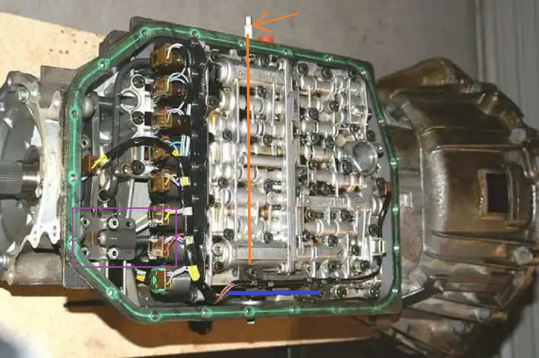
The shift rod is in orange. It has the F125 attached where the arrow is, runs inside the transmission over the valve body, and actuates 2 things:
In blue, the valve body 'primary control valve' (my name, ZF probably call it a spurving grammeter or something similarly arcane). This controls fluid flow from the pump to the backwards and forwards bits of the valve body and clutch packs (D, N and R). With no electronic overlord, moving this valve via the lever results in it engaging the 4th gear, or reverse clutch packs instantaneously with full line pressure - a hard slam in to gear. This is limp mode.
The TCU and its bank of solenoids (to the left of the valve body) modify these fluid paths (they do not define them). So the TCU can modulate line pressure to the clutch packs to smoothly engage gears, or it can change the fluid path in D from 4th gear to the correct clutches for gears 1 to 5. What it can't do is put the transmission in to R when this mechanical valve is sending the fluid to D, and I think bad things would happen if it tried, for example engaging two opposing clutch packs.
In purple, the parking pawl (P) engages a pin in to a slotted gear to lock the transmission solid.
There are also two speed sensors in here - you can see them at either end of the valve body. One for input from the engine, one for output from the gear cluster. This is how the TCU it determines 'gear ratio incorrect'. It has lookup tables for each gear so it knows this many rpm coming in should equal that many rpm going out. When these don't match (burned / slipping clutches or exploded A drum) then it logs the gear ratio code, shuts down leaves the transmission to run in its base hydromechanical mode (limp mode).
Re: Re-engineering the F125, a philosophical discussion
Thanks very much for that MJ, not a place I've ever looked at before, though I was vaguely aware of the two speed sensors and how the gearbox detected/reported incorrect ratios.
I have a lazy/nasty habit on level ground of not applying the handbrake, is that likely to damage the parking pawl?
Can you comment on how the shifter/ignition interlocks work and if that's independent of the F125/TCU; I thought relays but I'm sure I read somewhere long ago there was a Bowden cable involved?
I have a lazy/nasty habit on level ground of not applying the handbrake, is that likely to damage the parking pawl?
Can you comment on how the shifter/ignition interlocks work and if that's independent of the F125/TCU; I thought relays but I'm sure I read somewhere long ago there was a Bowden cable involved?
-
MikkiJayne
- Posts: 243
- Joined: Wed Sep 06, 2023 6:26 pm
Re: Re-engineering the F125, a philosophical discussion
Oh yeah forgot that bit. So there are two parts to the interlocks:
1, key interlock - this is indeed a bowden cable between the shifter and the ignition barrel. In anything other than P it mechanically locks the key in the barrel. I remove this from all mine because its a right pain to have to leave the key in with the car on the lift, especially if the battery is still connected.
2, brake interlock - this is a solenoid in the shifter body which puts a pin in the lever to prevent it moving in to gear unless the TCU sees the brake light signal. This is non-functional without power.
The parking pawl is a 10mm thick chunk of hardened steel which engages in slots in an equally chunky cog. Its not going anywhere, especially on level ground
1, key interlock - this is indeed a bowden cable between the shifter and the ignition barrel. In anything other than P it mechanically locks the key in the barrel. I remove this from all mine because its a right pain to have to leave the key in with the car on the lift, especially if the battery is still connected.
2, brake interlock - this is a solenoid in the shifter body which puts a pin in the lever to prevent it moving in to gear unless the TCU sees the brake light signal. This is non-functional without power.
The parking pawl is a 10mm thick chunk of hardened steel which engages in slots in an equally chunky cog. Its not going anywhere, especially on level ground
Re: Re-engineering the F125, a philosophical discussion
Thanks MJ, I understand now. So the TCU IS involved in the shifter lock but only in the sense that it needs power (obviously) and the brakes on signal to trigger the solenoid to get out of P. Nothing to do with the F125. 
Re: Re-engineering the F125, a philosophical discussion
Back on F125 contacts; this is how I "think" it works:
There are two "sides" to the F125 corresponding to the two contact arms swivelled by the central shaft. 4-contact and 5-contact arms.
The BMW unit (as noted earlier) does not have contacts or wiring for the 4-contact side, but presumably still communicates happily with their TCU.
This simpler BMW wiring was unknown to me until I started investigating a few days ago, but is consistent with my earlier assumptions.
IMHO the 4-contact side has just two separate 2-wire circuits which both carry significant power and these are not used in any way by the TCU:
1. Starter relay, allows starting only when in P or N, overridden by putting a link in place of the relay as in manual cars. Maybe the TCU is "aware" when the starter is actually active but putting the link in made no difference to normal operation in my car so I don't think it sees that circuit?
2. Reversing lights, this is the very long (red/blue maybe?) cable that goes right to the boot lid to power the reversing lights and (incidentally) provides the R signal to the RNS. This is the circuit where the contacts can easily become burnt as it can carry significant current for several seconds. I don't think the TCU has any awareness of this circuit. As noted earlier cars of this age don't actually need reversing lights to pass an MOT, but you do need a working starter!
FYI I have replaced my reversing light bulbs with much lower power (but brighter) LEDs and I also drive 3 parts of my reversing camera system from the same circuit with (so far) no ill effects, my F125 problems have been elsewhere. The 3 parts are 1. Camera 2. Video transmitter (in boot lid) and 3. Video receiver (near RNS), all activated only when R is selected. There's a 4th component, a CVBS-RGB video converter but IIRC that's run off the RNS power as I used to use it for TV input.
The 5-contact side (where I have definitely seen damaged contacts, see attached before and after images) I'll comment on later, but basically I think this section is what the TCU uses to read what the shifter is doing. Maybe a delve into the wiring diagram would help clarify?
There are two "sides" to the F125 corresponding to the two contact arms swivelled by the central shaft. 4-contact and 5-contact arms.
The BMW unit (as noted earlier) does not have contacts or wiring for the 4-contact side, but presumably still communicates happily with their TCU.
This simpler BMW wiring was unknown to me until I started investigating a few days ago, but is consistent with my earlier assumptions.
IMHO the 4-contact side has just two separate 2-wire circuits which both carry significant power and these are not used in any way by the TCU:
1. Starter relay, allows starting only when in P or N, overridden by putting a link in place of the relay as in manual cars. Maybe the TCU is "aware" when the starter is actually active but putting the link in made no difference to normal operation in my car so I don't think it sees that circuit?
2. Reversing lights, this is the very long (red/blue maybe?) cable that goes right to the boot lid to power the reversing lights and (incidentally) provides the R signal to the RNS. This is the circuit where the contacts can easily become burnt as it can carry significant current for several seconds. I don't think the TCU has any awareness of this circuit. As noted earlier cars of this age don't actually need reversing lights to pass an MOT, but you do need a working starter!
FYI I have replaced my reversing light bulbs with much lower power (but brighter) LEDs and I also drive 3 parts of my reversing camera system from the same circuit with (so far) no ill effects, my F125 problems have been elsewhere. The 3 parts are 1. Camera 2. Video transmitter (in boot lid) and 3. Video receiver (near RNS), all activated only when R is selected. There's a 4th component, a CVBS-RGB video converter but IIRC that's run off the RNS power as I used to use it for TV input.
The 5-contact side (where I have definitely seen damaged contacts, see attached before and after images) I'll comment on later, but basically I think this section is what the TCU uses to read what the shifter is doing. Maybe a delve into the wiring diagram would help clarify?
You do not have the required permissions to view the files attached to this post.